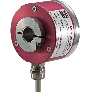
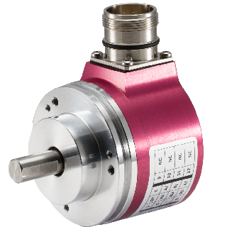
What is an incremental encoder ?
Incremental encoders are rotary automation components (angle sensors).
They are the first link in a chain of automation.
They exist in several technologies :
- In optical technology (the most common)
- In magnetic technology
- In inductive technology
Whatever the technology used, they provide an incremental signal processed by a PLC or a computer (processing unit) by counting up/ counting down the pulses generated by the incremental encoder.
The incremental encoder is mechanically integral with the drive axis (motor; machine tool axes; cable sensors; robots, etc.).
The output signals are pulse trains generally on 6 channels for counting up/down and 12 (6 + 6) if they are also used for phase commutations (U; V; W) of electric motors.
How does an incremental encoder work : technologies
Optical encoder
Optical incremental encoders, as the name suggests, work with optical technology. The centerpiece of the reading system is the glass or polycarbonate code disc. On the disc are engraved very precise and equidistant slots which define the number of pulses (resolution) per revolution of the encoder. A light emitting component, mostly an LED (Light Emitting Diode) emits light in the infrared i.e. with a wavelength of 850 nm and a sensitive receiver infrared light.
The receiver is an electro-optical component of very high integration. For example, there are photodiodes, op amps, Schmitt triggers, comparators, regulators, etc. on a 5 × 5 mm chip. The diaphragm, essential part which is often stuck on the, has a function of “guide of the light” to channel the photons towards the receiving photodiodes.
Magnetic incremental encoders
There are two well-known principles for magnetic reading:
- Reading by central magnet
- Reading by magnetic disc
Incremental encoders with a central magnet
A cylindrical samarium – cobalt (SmCo) or neodymium (NdFeB) magnet placed in the center of the incremental encoder drive axis is made up of 2 poles (north and south).
When the magnet turns, it causes a potential difference across the Hall cells. This signal (potential difference) is sinusoidal and is equivalent to one sinusoid per encoder revolution (0 to 360°).
Encoder with central magnet
Advantages of the magnetic reading :
- The encoder can whitstand high temperatures (more than 120°C)
- Simple conception
- Easy assembly and adjustment
- Lower requirement for precision
- Possible miniaturization
- operation in harsh environments (electric motors)
- Low cost
Inconvenients of the magnetic reading :
- Low precision
- Low resolution (1024 points per revolution)
- High jitter due to the interpolation of the single sinusoidal signal for an encoder turn
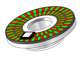
Incremental encoder with magnetic disc
This principle works like the optical encoder but the technology used is magnetic.
The magnetic disc is divided into several magnetic zones (64 north and south pole pairs).
- Better accuracy on duty cycles and on phase shift. Less than the optical disc but significantly better than the principle with the central magnet
- A single processing PCB instead of 2 on the optical reading
- Possibility of high resolution (up to 65536 points per revolution)
Inductive incremental encoder
Inductive encoders are remarkable encoders for their robustness, their resistance to temperature, vibrations, accelerations and their precision.
The technology used to read a target (disc) is the induction.
The target made of ferromagnetic conductive materials (copper) is etched on a substrate (the most common is FR4).
Inductive technology has been known since 1833, stated by Heinrich Emil LENZ, Russian physicist. But the essential elements of this type of encoder are the differential coils traversed by a high frequency current which produce in the space surrounding its ends a variable electromagnetic field.
When the conductive track of the engraved disc enters this zone, it will be the seat of eddy currents, and according to the law of LENZ, these currents oppose the cause which gave them birth and therefore create an induction in the contrary direction to the induction of the coils, which leads to a reduction in its self-induction coefficient.
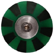
Inductive differential disc
With regard to the 2 photos above, two reading principles are possible:
-
Standard reading which functions as an inductive proximity switch
-
Differential reading is best suited for inductive encoders, it guarantees better immunity to electromagnetic disturbances generated by inductive external loads such as motors, drives, solenoid valves etc. Differential reading works according to the well-known differential transformer principle, which has long proven itself with LVDT (Linear Variable Differential Transformer) sensors.
-
A high frequency sine wave (1 – 2 MHz) travels through the primary coil of the transformer and generates an electromagnetic field. The two secondary coils are arranged in a perfectly symmetrical differential configuration with respect to the primary coil. The alternating electromagnetic field generated by the primary coil induces in each of the secondary coils a voltage according to the law of Michael Faraday (1791-1867 English physicist, chemist): (E = -dΦ / dt).
Each technology has its advantages and disadvantages
Characteristics and accuracy of output signals
We distinguish 2 signals called channel A (in yellow) and channel B (in green). For a clockwise rotation direction (clockwise with view on the axis of the encoder), we note that the 1st rising edge of signal B (green) rises before the 1st rising edge of A (yellow). It’s thanks to this order that the signal processing electronics can know the direction of rotation of the encoder. This is called the discrimination of rotation direction.
A, B, Z signals on an oscilloscope
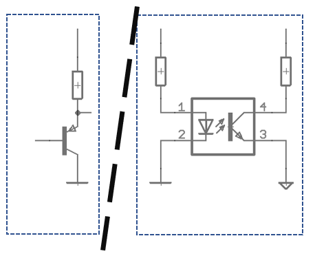
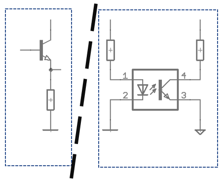
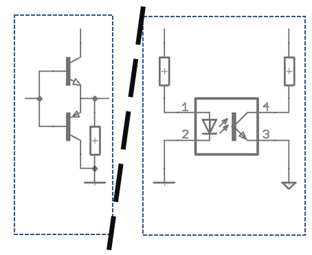
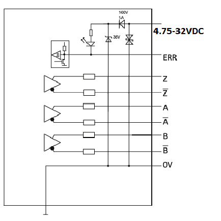
The transistored output stages are very rarely used any more. They are replaced by specific integrated circuits with protections against reverse polarity; overvoltages; short circuits; excessive temperatures and allow very high output frequencies, on the order of MHz.
Output with integrated circuits :
Frequently asked questions
What is a duty cycle ?
On the diagram below, the duty cycle corresponds to T. The duty cycle is expressed in %.
If T = 100% then T/2 = 50% and corresponds to twhi on the diagram.
The maximum tolerance is +/- 10%, i.e. twhimax = 60% and twhi mini = 40%. Or A Arel = 20%
What is a phase shift?
The phase shift is the position of channel A with respect to channel B. This corresponds to the value TAB on the diagram above. he theoretical value of T AB is 90 ° electrical. The tolerance for the TAB value is 25%. Then TAB max = 112.5 ° and T AB mini = 67.5 °
What is jitter?
In theory, channels A and B should have exactly the same duty cycle. In reality, there is a gap, called “jitter”. The jitter comes from many factors: type of encoder (quality and placement of the disc or magnet), rotation speed, encoder resolution, etc.
What is an output frequency?
The output frequency of an incremental encoder corresponds to the resolution multiplied by the speed of rotation of the encoder shaft.
F = R * RPM (F = frequency; R = Encoder resolution; RPM = encoder rotation in revolutions per minute
Example: for a resolution encoder of 5000 points per revolution and which rotates at a speed of 3000 rpm
5000×3000 = 15,000,000 points per minute i.e. 15,000,000 / 60 = 250,000 Hz = 250 kHz
How to check the good working condition of an encoder?
A minimum of equipment is required: everyone has at least one multimeter in their toolkit.
A very important value is the consumption without load of the encoder, and for most recent design encoders, this consumption is between 30 and 90mA.
If the incremental encoder consumes 0 mA, there is a good chance that the polarity reversal protection diode is defective but before that it must be checked whether the supply voltage (5 to 32 volts DC, see encoder characteristics) is present at the input of the encoder. On machine-tools, the encoder power cables are subjected to oil vapors and lubricants which are often the cause of cable hardening. It is this stiffening of the cable that causes it to break and very often flush with the connector.
If the encoder were to consume several amps, there is a good chance that a TVS has amorced and has short-circuited. In this case I advise to send it back to the factory for in-depth expertise. If a TVS has short-circuited, the cause must be investigated on the site.
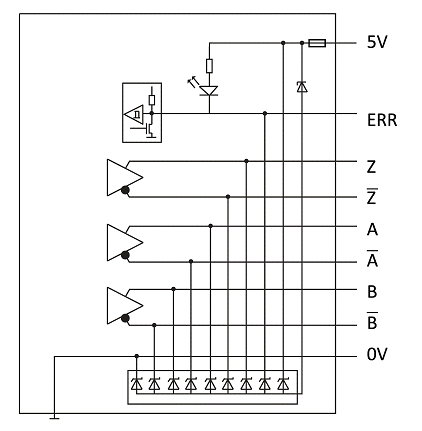
This first test carried out (5 to 32 Vdc OK, consumption without load between 30 and 90 mA OK) and still no output signal, we strongly recommend looking directly at the encoder output to be sure to eliminate all the problems that could be linked to the transmission cable between encoder and PLC.
Check the output signals.
For this test we can use several types of instruments: The multimeter; the oscilloscope or simply an LED with a resistor in series.